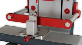
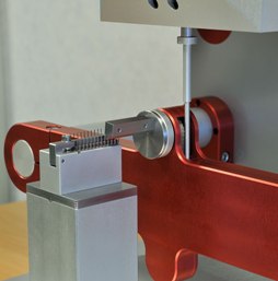
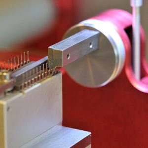
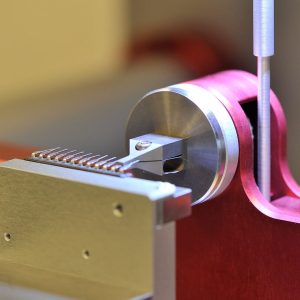
Lead integrity/micro torsion
Our lead integrity test method provides various tests for determining the integrity of microelectronic device leads (terminals), welds, and seals. There are 4 different test conditions which can be performed.
- Test condition “A” provides for straight tensile loading.
- Test condition “B1” provides for application of bending stresses to determine integrity of leads, seals, and lead plating while “B2” employs multiple application of bending stresses primarily to determine the resistance of the leads to metal fatigue under repeated bending.
- Test conditions “C1” and “C2” provide for application of torque or twisting stresses to device leads or studs, respectively, to determine integrity of leads and seals.
- Test condition “D” provides for application of peel and tensile stresses to determine integrity of terminal adhesion and plating of leadless packages.


Test condition A – Tension
This test is designed to check the capabilities of the device leads, welds, and seals to withstand a straight pull. A tension of 0.227 kgf shall be applied, without shock, to each lead or terminal to be tested in a direction parallel to the axis of the lead or terminal and maintained for 30 seconds minimum. The tension shall be applied as close to the end of the lead (terminal) as practicable.
When examined using 10X magnification after removal of the stress, any evidence of breakage, loosening, or relative motion between the lead (terminal) and the device body shall be considered a failure.
Test condition B1 – Bending Stress
This test is designed to check the capability of the leads, lead finish, lead welds, and seals of the devices to withstand stresses to the leads and seals which might reasonably be expected to occur from actual handling and assembly of the devices in application, or to precondition the leads with a moderate bending stress prior to environmental testing.
Each lead or terminal to be tested shall be subjected to force sufficient to bend the lead. Any number or all of the leads of the test device may be bent simultaneously. Rows of leads may be bent one row at a time. Each lead shall be bent through one cycle as follows: Bend through the specified arc in one direction and return to the original position. All arcs shall be made in the same plane without lead restriction.
When examined using magnification between 10X and 20X after removal of the stress, any evidence of breakage, loosening, or relative motion between the terminal lead and the device body shall be considered a device failure.

Test condition B2 – Lead Fatigue
This test is designed to check the resistance of the leads to metal fatigue.
The appropriate procedure for the device under test equals to test condition B1, however the leads to be tested shall be subjected to three cycles.
A broken lead on a device shall be considered a failure. When examined using magnification between 10X and 20X after removal of the stress, any device which exhibits any evidence of breakage, loosening, or relative motion between the terminal lead and the device body shall be considered a device failure.
Test condition C1 – Lead Torque
This test is designed to check device leads (or terminals) and seals for their resistance to twisting motions.
The device body shall be rigidly held and the specified torque shall be applied for 15 seconds minimum to the lead (terminal) to be tested, without shock, about the axis of the lead (terminal).
When examined using magnification between 10X and 20X after removal of the stress, any evidence of breakage, loosening, or relative motion between the terminal (lead) and the device body shall be considered a device failure.

Test condition C2 – Stud Torque
This test is designed to check the resistance of the device with threaded mounting stud to the stress caused by tightening the device when mounting.
The device shall be clamped by its body or flange. A flat steel washer of a thickness equal to six thread pitches of the stud being tested and a new class 2 fit steel nut shall be assembled in that order on the stud, with all parts clean and dry. The specified torque shall be applied without shock to the nut for the specified period of time. The nut and washer shall then be disassembled from the device, and the device then examined for compliance with the requirements.
The device shall be considered a failure if any of the following occurs:
- The stud breaks or is elongated greater than one-half of the thread pitch.
- It fails the specified post-test end point measurements.
- There is evidence of thread stripping or deformation of the mounting seat.
Test condition D – Solder Pad Adhesion
This test is designed to check the capabilities of the device solder pads to withstand a delamination (peel) stress of specified tension and time.
Delamination (peel) stress test shall be applied to randomly selected solder pads from each device selected for test. Pretinned soft annealed solid copper wire shall be soldered to each solder pad to be tested in a manner such that the wire is bonded over the entire solder pad length and terminates at the package edge. The unsoldered portion of the wire shall be bent perpendicular to the bond plane prior to attachment. Caution should be taken to assure that the solder pad metallization is not damaged during the soldering or the wire bending operation. A minimum tension of 2.22 N shall be applied, without shock, to each solder pad to be tested in a direction perpendicular to the solder pad surface and maintained for 30 seconds minimum.
When examined, using 10X magnification, after removal of the tension stress, the appearance of any delamination involving constituent solder pad interfaces shall be considered an adhesion failure of the solder pad. Separation of the solder pad from the device is an obvious (without visual magnification) adhesion failure. Separation of the wire from the solder fillet (leaving the solder pad intact) or wire breakage is considered a test procedure failure.
How to: Lead integrity test
Standards
- MIL-STD-883 METHOD 2004.7
- JEDEC-22 METHOD B105D
Test features
- Retrofit module
- Unique solution, nowhere else available
