Total ball shear/zone shear
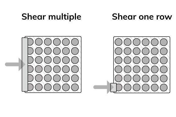
Total Ball Shear (TBS) or zone shear tests all or many rows of balls in one operation, producing more bond or pad failures. Using a wide-shear tool, it is possible to shear multiple rows of solder balls in a single stroke. Apply the test before the second level attachment to the printed wiring board of the BGA. The shear speed must be constant throughout the complete shear stroke. Typically the speed is set between 5 to 50 mm/s.
Total Ball Shear testing does not provide any relevant force measurement data. Still, it does provide a visually inspected outcome of the metallurgical joint between the solder ball and BGA pad metallization. As hundreds of solder balls are tested at one time, the very scarce brittle fractures on a single solder ball become visible for inspection. However, more common low-speed solder ball shear tests on one single solder ball do provide relevant force measurement data.
Therefore TBS testing offers a fast, low cost and easy solution for obtaining substantial statistical information on the brittle versus ductile fracturing of lead-free solder balls. Although it replaces the more time-consuming high-speed shear testing for in-line BGA production process control, it cannot provide the relevant measurement metrics like high speed shear testing would in a research environment.
Standards
- JEDEC standard JESD22-B117
Test features
- Fast, destructive, inline testing of lead-free BGA’s
- Testing hundreds of solder balls simultaneously
- Brittle fracture outcome by visual inspection
- Test speed from 5 mm/s to 50 mm/s
- Stress testing of BGA modules
Failure mechanism
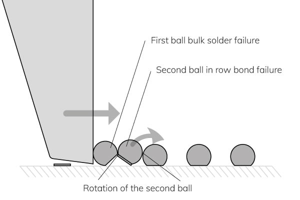
Below is an example of the failure mechanism. The rotation of the second ball is not free. This requires some sliding at the contacts because of ball deformation at the contact points.
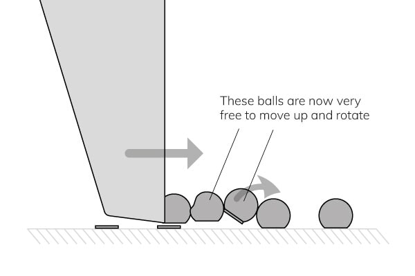
When the second ball in the row fails, its restricted movement produces a bulk solder failure, even though the first ball sheared it. The movement of the third ball in the row is less restricted because it is loaded by the second ball, which can easily move.
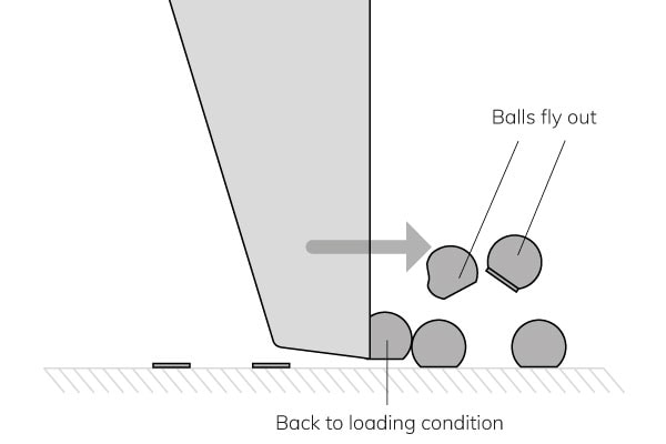
The sudden load release on the third row causes these balls to fly out. So, after the failure of row one, we are back to the loading condition.
The first ball may also fly off after the third ball’s failure, but it does tend to stick to the tool. In this case, the cycle repeats at the fourth ball in the row.
Note that the typical importance of tool shear height is less critical for balls generally tested by the previous ball. Therefore, it is an estimation that a shear height between 1% to 15% of the ball height is acceptable.


